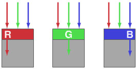
Unfortunately, there is no simple way to have a single pixel simultaneously measure the red, green and blue light falling on it. A red filter placed above a pixel allows just the red portion of the incoming light to pass through and blocks the green and blue portions (see Figure 6). Similarly, green and blue filters allow pixels to measure only the green and blue components of the light, respectively.
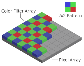
Figure 7: Bayer color filter array
Bigshot’s image sensor, like most image sensors, employs a mosaic of tiny red, green and blue color filters, each filter positioned just beneath the microlens of a pixel. A popular design for the mosaic is the Bayer pattern [1] shown in Figure 7. Now the question is, how do we estimate the red, blue and green light falling on any given pixel, if it is able to receive only one of the three colors − red, blue or green?
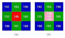
Figure 8: Color interpolation
Figure 8a shows a 3×3 grid of pixels in the Bayer pattern. Let us assume the number at each pixel to be the amount of red, green, or blue light it detects. For example, the red component of the center pixel is 246, but its green and blue components are unknown. The two missing colors are estimated using the green and blue measurements made by neighboring pixels. This process is called interpolation.
The simplest way to interpolate the missing values is to average the values of neighboring pixels of the same color (see Figure 8b). So, the interpolated value of the green component at the center pixel is (163+165+161+155)/4=161. The interpolated value of the blue component is (192+190+186+188)/4=189. The detected red value along with the interpolated green and blue values together make up the final color (246, 161, 189) of the pixel shown in Figure 8b.
This way, each pixel will have three values − the actual value of the color it measures through its filter, as well as two interpolated values for the two missing colors. The interpolation is applied to each and every pixel to obtain a full color image. The color interpolation process is known as demosaicing [2]. Click on the play button in Figure 9 to see demosaicing in action.


 References